Showing posts with label Switching Circuits. Show all posts

Sunday, 21 April 2013

Load Sensing Automatic Switch

Description

The circuit of the mains current detector is shown in Figure 1.  By using a few cheap diodes, a resistor, LED and LDR, a simple opto-isolated detector can be created.  This entire circuit dissipates very low power, and can safely be housed in a heatshrink wrapper to ensure that contact with live wiring is not possible.  This will also keep light away from the LDR.  These are cheap and easy to use.  I found that I could detect as little as 10mA of mains current with this circuit, and no distress was created at 0.5A.  The diodes will get very warm at higher currents.

Note that because of the 1A diodes used, this is the absolute maximum current of the switched load.  If a higher current is expected, you must use high current diodes to prevent failure.  I shall leave it to the reader and the local electronics supplier to select suitable devices.  Voltage rating is not important, as they are in series with the load.  Don't be tempted to use Schottky diodes to reduce the loss - you need the loss to turn on the LED.

Automatic Headlight Brightness Switch


Driving the highway with your high-beam headlights can really increase your visibility, but can be a blinding hazard for other drivers. This simple circuit can be wired into your headlight switch to provide automatic switching between high and low beam headlights when there is oncoming traffic. It does this by sensing the lights of that traffic. In this way, you can drive safely with your high-beams on without blinding other drivers.

Automatic Switch For Audio Power Amplifier

Circuit of an automatic switch for audio power amplifier stage is presented here. The circuit uses stereo preamplifier output to detect the presence of audio to switch the audio power amplifier on only when audio is present. The circuit thus helps curtail power wastage. IC1 is used as an inverting adder. The input signals from left and right channels are combined to form a common signal for IC2, which is used as an open loop comparator. IC3 (NE556) is a dual timer. Its second section, i.e., IC3(b), is configured as monostable multivibrator. Output of IC3(b) is used to switch the power amplifier on or off through a Darlington pair formed by transistors T1 and T2. IC3(a) is used to trigger the monostable multivibrator whenever an input signal is sensed. 
Click On Circuit to view Large

HEAT-SENSITIVE SWITCH

At the heart of this heat-sensitive switch is IC LM35 (IC1), which is a linear temperature sensor and linear temperature-to-voltage converter circuit. 
The converter provides accurately linear and directly proportional output signal in millivolts over the temperature range of 0°C to 155°C. It develops an output voltage of 10 mV per degree centigrade change in the ambient temperature. Therefore the output voltage varies from 0 mV at 0°C to 1V at 100°C and any voltage measurement circuit connected across the output pins can read the temperature directly. 
The input and ground pins of this heat-to-voltage converter IC are connected across the regulated power supply rails and decoupled by R1 and C1. Its temperature-tracking output is applied to the non-inverting input (pin 3) of the comparator built around IC2. The inverting input (pin 2) of IC2 is connected across the positive supply rails via a voltage divider network formed by potmeter VR1.
Click on Immage to view large

Intelligent switch

This intelligent switch circuit en- ables automatic switching on of an emergency light system during darkness in the event of mains failure. The mains power failure condition is detected by the section consisting of mains step-down transformer X1 followed by bridge rectifier comprising diodes D1 through D4 and smoothing capacitor C1. If the mains is available then it causes energisation of relay RL1 which has two sets of changeover contacts. 

Electronic Door Release

Description

This circuit is designed to operate an electrical door-release mechanism - but it will have other applications. Enter the four-digit code of your choice - and the relay will energize for the period of time set by C4 & R4. Use the relay contacts to power the release mechanism. The standby current is virtually zero - so battery power is a realistic option.

The circuit is drawn with a 12-volt supply - but it will work at anything from 5 to 15-volts. All you have to do is choose a relay suitable for the supply voltage you want to use. Replace the SPCO/SPDT relay with a multi-pole relay - if it suits your application.

Important: Do not use the "on-board" relay to switch mains voltage. The board's layout does not offer sufficient isolation between the relay contacts and the low-voltage components. If you want to switch mains voltage - mount a suitably rated relay somewhere safe - Away From The Board.

Keypad Switch No. 2

Description

This is a simplified version of the Universal Keypad-Operated Switch. I have modified the design to reduce the complexity of the circuit - and the number of components required. As a result - the code is somewhat less secure. However, there should be lots of situations where it will still be adequate. 

The circuit is drawn with a 12-volt supply - but it will work at anything from 5 to 15-volts. All you have to do is choose a relay suitable for the supply voltage you want to use. Replace the SPCO/SPDT relay with a multi-pole relay - if it suits your application. 


Important: Do not use the "on-board" relay to switch mains voltage. The board's layout does not offer sufficient isolation between the relay contacts and the low-voltage components. If you want to switch mains voltage - mount a suitably rated relay somewhere safe - Away From The Board. 


VCS using 555 Timer

Description

In this circuit the 555 timer is used in a novel way, as a voltage controlled switch.


Motor Reversing Circuit


Description

Motor cannot be switched from forward to reverse unless the stop switch is pressed first.

Voltage Comparator

Description

This circuit will provide an indication whenever the input voltage differs from two defined limits, V1 and V2. The limits are adjustable and the circuit made to trigger from the adjustable "window". 

Saturday, 20 April 2013

Sound Operated Switch

Description

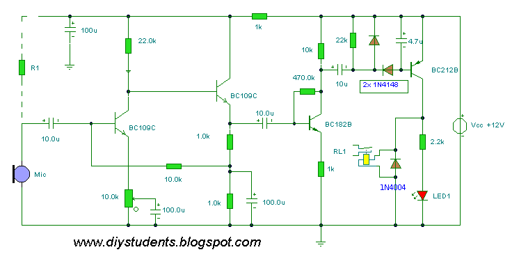
A sound operated switch with a relay driver.

Electronic Night Light


Description

This circuit for an electronic night light was submitted by Adam from Canada. I have provided the notes.

Digital Combination Lock

Description

A multiple input combination loack using CMOS counter IC's. Flexibility and code change is allowed by changing output connections.
Click on Immage to view Large

Electronic Doorbell with Counter

Description

This circuit uses a synthesized sound chip from Holtek, the HT-2811. This reproduces the sound of a "ding-dong" chiming doorbell. Additionally, the circuit includes a CMOS 4026 counter display driver IC to count your visitors.


Doorbell Warning Switch


Description
This circuit will light a lamp at a remote location when the doorbell switch is pressed. This circuit should only be used with the solenoid type doorbells, the electronic type that play tunes will not work here. 


Notes
It is quite easy to miss the sound of a doorbell if you are watching TV , this circuit gets round the problem by providing a visual indication. As an alternative, a LED could also be used. You could just parallel a lamp across the doorbell, but this would mean extra drain from the doorbell batteries or transformer.

A series resistor, R1 is wired in series with the doorbell and reduces current flow, thereby increasing battery life. The value of R1 is chosen so that about 0.6 to 0.7 volts is developed across it, when the doorbell switch is pressed. I used a combination of a 22 ohm resistor in parallel with a 50 ohm. The voltage drop across R1 is sufficient to switch on the transistor, the lamp in series with the collector will then illuminate. I also used an electromechanical counter in parallel with the lamp. This registered each time someone pressed the switch....in fact, I can remember a time when I had more "hits" on my doorbell counter then at my web site :) 

Light Detector Circuit


Notes

Variable resistor R1 adjusts the light threshold at which the circuit triggers. R1's value is chosen to match the photocells resistance at darkness. The circuit uses a CMOS 4001 IC. Gate U1a acts as the trigger, U1b and c form a latch. S1 resets the circuit. The output device may be a low power piezo buzzer.

Switch De-Bouncer


Description

This circuit will remove the transient spikes and contact bounces from a non-latching push button switch.


DC Motor Control


Description

control of the movement of the motor, and an indication of direction provided by LED's.


Electronic Door Release

Description

The IC is a quad 2 input "AND" gate, a CMOS 4081. These gates only produce a HIGH output, when BOTH the inputs are HIGH. When the key wired to 'E' is pressed, current through R1 and D1 switchs Q5 on.The relay energises; and Q5 is 'latched on' by R8. Thus, the Alarm is set by pressing a single key,say one of the two non-numeric symbols. 


Dark Activated Switch

Description

This circuit will activate a relay when light falls to a preset level. Light level can be adjusted with VR1 and the relay contacts may be used to operate an external light or buzzer.