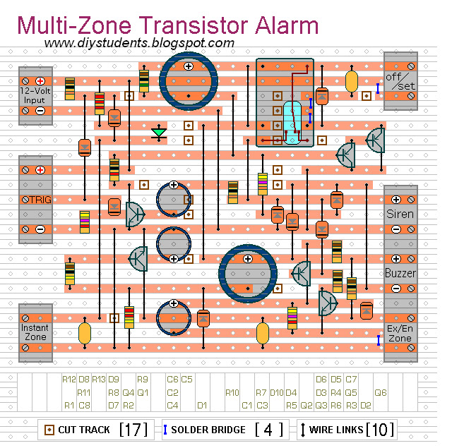
This is a simple transistor based burglar alarm circuit. Its features include automatic Exit and Entry delays - together with a timed Bell cut-off and Reset. It's designed to be used with the usual types of normally-closed input devices such as - magnetic-reed contacts - micro switches - foil tape - and PIRs.
The basic alarm has an "Exit/Entry" zone and an "Instant" zone. This will be adequate in many situations. However - larger buildings are best divided into a number of smaller zones. The alarm's modular design means that you can Add As Many Zones As You Like to the system. They are "Instant Zones" - and may be triggered by both normally-open and normally-closed input devices.
It's easy to use. Make sure that the green LED is lighting - then switch the alarm on using Sw1. You have about 30 seconds to leave the building. When you return and open the door - the Buzzer will sound. You have about 30 seconds to switch off the alarm. If you fail to do so - the Siren will sound.
While at least one of the trigger switches remains open - the Siren will continue to sound. However - if the trigger circuits have been restored - the alarm will reset itself after about 10 minutes. Of course - you can turn the Siren off at any time by switching off the alarm.
Because of manufacturing tolerances - the precise length of any delay depends on the characteristics of the actual components you've used in your circuit. But - to some degree - by altering the values of R2, R7 & R9 you can adjust the Exit, Entry and Reset times to suit your requirements. Increasing the values increases the time - and vice-versa.
If you don't want the "Instant" zone - leave out D7, D8, D9, R12, R13, C8 and the Green LED.


This article is really informative about making of transistor based burglar alarm. Professional home security like wireless burglar alarm is basic need of every home and business. You can monitor your home, property 24/7 from anywhere even you are not at home. Thanks for share your efforts.
ReplyDelete