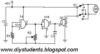
I found this circuit in my files. I don't know where it came from, but it looks like I photocopied it from somewhere years ago. I have been told that it came from "The Robot Builder's Bonanza", by Gordan McComb. Anyway, I thought that it should be fairly useful, so I decided to post it here. The circuit is very simple and inexpensive. This is good thing because most commercial stepper motor controller ICs are quite expensive. This circuit is built from standard components and can easily be adapted to be controlled by a computer. If you use cheap surplus transistors and stepper motor, the price of the circuit can be kept to under $10.
Showing posts with label Motor Speed Control. Show all posts
Sunday, 21 April 2013
Simple Two Speed Contactor DC Motor Controller
The simplest of all motor controllers (besides a straight on/off switch) is the contactor controller. I designed this contactor controller for use in my electric scooter project. It is based around three 12V relays, two 12V batteries, two switches and of course a motor. Having no silicon to "fry", it is quite reliable and robust. A contactor controller works by rearranging the two (or more) supply batteries between series and parallel. This gives the motor a slow speed (batteries in parallel, current adds) and a fast speed (batteries in series, voltage adds). This assures that both batteries are discharged equally. When the circuit is "at rest", the batteries are connected in parallel, which allows easy recharging.
Simple Servo Controller
Servo motors have many uses in everything from robotics to puppetry to photography and beyond. These little motors can position their output shaft to any position on command and hold that position. Most servos have a range of motion to about 210 degrees and thankfully are very easy to control with a simple circuit such as the one presented here. Using just a 555 timer and a few support components this circuit can control a servo through it's full rotation based on the position of a pot. This circuit was originally published in the Think Tank column of the October 1995 issue of Popular Electronics.
Pulse Width Modulation DC Motor Control
Often, people attempt to control DC motors with a variable resistor or variable resistor connected to a transistor. While the latter approach works well, it generates heat and hence wastes power. This simple pulse width modulation DC motor control eliminates these problems. It controls the motor speed by driving the motor with short pulses. These pulses vary in duration to change the speed of the motor. The longer the pulses, the faster the motor turns, and vice versa.
AC Motor Speed Controller
This AC motor speed controller can handle most universal type (brushed) AC motors and other loads up to about 250W. It works in much the same was a light dimmer circuit; by chopping part of the AC waveform off to effectively control voltage. Because of this functionality, the circuit will work for a wide variety of loads including incandescent light bulbs, heating elements, brushed AC motors and some transformers. The circuit tries to maintain a constant motor speed regardless of load so it is also ideal for power tools. Note that the circuit can only control brushed AC motors. Inductive motors require a variable frequency control.
Subscribe to:
Posts (Atom)