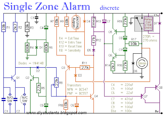
This circuit features automatic Exit and Entry delays - timed Bell/Siren cut-off - and system reset. It has provision for normally-open and normally-closed switches - and will suit all of the usual input devices (Pressure Mats, Magnetic Reed Contacts, Foil Tape, PIRs and Inertia Sensors).
Showing posts with label ALARM / Doorbell PROJECT. Show all posts
Saturday, 20 April 2013
A Multi-Zone Transistor Based Burglar Alarm
This is a simple transistor based burglar alarm circuit. Its features include automatic Exit and Entry delays - together with a timed Bell cut-off and Reset. It's designed to be used with the usual types of normally-closed input devices such as - magnetic-reed contacts - micro switches - foil tape - and PIRs.
The basic alarm has an "Exit/Entry" zone and an "Instant" zone. This will be adequate in many situations. However - larger buildings are best divided into a number of smaller zones. The alarm's modular design means that you can Add As Many Zones As You Like to the system. They are "Instant Zones" - and may be triggered by both normally-open and normally-closed input devices.
An SCR Based Burglar Alarm
This is a simple SCR based burglar alarm circuit. Its features include automatic Exit and Entry delays - together with a timed Bell cut-off and Reset. It's designed to be used with the usual types of normally-closed input devices such as - magnetic-reed contacts - micro switches - foil tape - and PIRs.
The basic alarm has a single zone with "Exit/Entry" delays. This will be adequate in many situations. However - larger buildings are better divided into zones. The modular design means that you can Add Any Number Of Zones to the system. These "Instant" zones may be triggered by normally-open as well as normally-closed input devices.
A One-Time-Only Alarm
This alarm is designed to sound its Siren only once. That is - when the alarm is activated - the Siren will sound for a preset length of time. Then it will switch off and remain off. The alarm will not re-activate.
The basic alarm has a single zone with independently adjustable Exit and Entry delays. The zone will accommodate the usual types of normally-open and normally-closed input devices - such as pressure mats, magnetic-reed contacts, micro switches, foil tape and PIRs.
A range of Expansion Modules allow you to add any number of Instant Alarm Zones, Personal Attack Zones and Tamper Zones to your system. There's also an Untimed Output Module. It will keep an internal sounder, strobe-light, lamp or whatever going after the siren has stopped.
Schematic Diagram
Two-Zone Alarm
This is a two-zone alarm - with automatic exit, entry and siren cut-off timers. It can be triggered by the usual types of normally-closed input devices - such as magnetic reed contacts - foil tape - PIRs etc. I've used a 12-volt supply in the diagram - but the circuit will work at anything from 9 to 15-volts. All you need do is select a siren, buzzer and relay to suit the voltage you want to use.
Schematic Diagram
Four Small Transistor Alarm Circuits
Alarm Circuit A
Alarm "A" is a practical version of the circuit featured in my Introduction To The Complementary Latch. It has both normally-open and normally-closed triggers. Once activated - the buzzer will go on sounding until the alarm is switched off. The standby current is less than 100uA. This is due exclusively to the value of R1. Depending on the gain of the actual transistors you're using - you may be able to increase the value of R1 - and so improve battery life.
Friday, 19 April 2013
simple siren using dual OP-AMP
Device such as burglar alarms and sirens, whose basic purpose is to monitor certain conditions, make enjoyable projects because of the verity of sounds they can generate. Figure 1 shows a simple siren/alarm circuit using a dual-amp MC1458, audio amplifier LM380, and a 1-W speaker. The dual op-amp is used as a signal generator that produces square, pulse and triangular or sawtooth wave froms.
Motor Bike Brake Horn
The circuit can be operated from 4.5V to 12V DC or direct from the brake point of the motor-bike, Resistor R7 should be replaced with 1-ohm. 1/2W in case of an 8-ohm speaker. T5 is a driver transistor. C3 polarity can be reversed for a sudden off of the circuit.
The sound produced is like “Kiun, Kiun”.
Thursday, 18 April 2013
The Yamaha Sound
No longer do you need to look wistful every time the guy on the TV rams home a power-chord on his big Yamaha DX synthesizer. With this ‘black box’ plugged in between your most non-descript organ and a good amplifier, you too can produce that very distinct but very familiar voice the zippy “Yamaha” sound.
Sound Operated Music Bell
Sometimes ringing the bell manually becomes difficult, especially when you are holding something in your hands. The sound-operated music bell takes care of the problem
In this circuit, the use of an external relay has been eliminated. The circuit comprises a trigger stage (around BC548B), a timer stage (NE555) and a melody stage (around UM66 and SL100).
Subscribe to:
Posts (Atom)


