Thursday 25 April 2013

RFID Module and Principle of working

RFID Module and Principle of working

RFID Reader Module, are also called as interrogators. They convert radio waves returned from the RFID tag into a form that can be passed on to Controllers, which can make use of it. RFID tags and readers have to be tuned to the same frequency in order to communicate. RFID systems use many different frequencies, but the most common and widely used & supported by our Reader is 125 KHz.

History and Scope of RFID


History and Scope of RFID
Radio-frequency identification (RFID) is a technology that uses communication through the use of radio waves to exchange data between a reader and an electronic tag attached to an object, for the purpose of identification and tracking.
HISTORY:
In 1945 Leon Theremin invented an espionage tool for the Soviet Union which retransmitted incident radio waves with audio information. Sound waves vibrated a diaphragm which slightly altered the shape of the resonator, which modulated the reflected radio frequency. Even though this device was a covert listening device, not an identification tag, it is considered to be a predecessor of RFID technology, because it was likewise passive, being energized and activated by waves from an outside source.

Analog to Digital Converter module


Analog to Digital Converter module
   Analog to Digital converter modules are used in Micro controller based projects where the analog signals are required to be converted into digital signal for further processing in Micro controller. The integrated chip used for this purpose is 0809 ADC. This post describe briefly the PIN diagram, block diagram and details of this specified chip here.
Pin Diagram
Circuit Diagram of ADC 0809

Relay Vs Switch


Relay Vs Switch
A relay is an electrically operated switch. Current flowing through the coil of the relay creates a magnetic field which attracts a lever and changes the switch contacts. The coil current can be on or off so relays have two switch positions and they are double throw (changeover) switches. 


Relays allow one circuit to switch a second circuit which can be completely separate from the first. For example a low voltage battery circuit can use a relay to switch a 230V AC mains circuit. There is no electrical connection inside the relay between the two circuits; the link is magnetic and mechanical. The coil of a relay passes a relatively large current, typically 30mA for a 12V relay, but it can be as much as 100mA for relays designed to operate from lower voltages. 

PROXIMITY SENSOR


PROXIMITY SENSOR
A proximity sensor detects an object when the object approaches within the detection boundary of the sensor. Proximity sensors are used in various facets of manufacturing for detecting the approach of metal objects. 
Various types of proximity sensors are used for detecting the presence or absence of an object. The design of a proximity sensor can be based on a number of principles of operation, some examples include: variable reluctance, eddy current loss, saturated core, and Hall Effect. Depending on the principle of operation, each type of sensor will have different performance levels for sensing different types of objects. 
Common types of non-contact proximity sensors include inductive proximity sensors, capacitive proximity sensors, ultrasonic proximity sensors, and photoelectric sensors. Hall-effect sensorsdetect a change in a polarity of a magnetic field. 

Digital to Analog Converter DAC 0800


Digital to Analog Converter : DAC 0800


Digital to Analog Converter(DAC 0800) with Current to Voltage converter(LM741)

In electronics, a digital-to-analog converter (DAC or D-to-A) is a device for converting a digital (usually binary) code to an analog signal (current, voltage or electric charge). Digital-to-analog converters are interfaces between the abstract digital world and analog real life. An analog-to-digital converter (ADC) performs the reverse operation. A DAC usually only deals with pulse-code modulation (PCM)-encoded signals. The job of converting various compressed forms of signals into PCM is left to codecs. Basic Operation: The DAC fundamentally converts finite-precision numbers (usually fixed-point binary numbers) into a physical quantity, usually an electrical voltage. 

Thermistor with OPAMP control circuit


Thermistor with OPAMP control circuit
Thermistor with LM324 OPAMP

A thermistor is a type of resistor used to measure temperature changes, relying on the change in its resistance with changing temperature. Thermistor is a combination of the words thermal and resistor. The Thermistor was first invented by Samuel Ruben in 1930.
If we assume that the relationship between resistance and temperature is linear (i.e. we make a first-order approximation), then we can say that: 
ΔR = Kδt 
Where ΔR = change in resistance ΔT = change in temperature k = first-order temperature coefficient of resistance

GPS Module GP810


The GP 810 receiver board is based on the high performance GP 810 receiver architecture. This 810 receiver is ideally suited for applications that require easy replacement for Trimble Lassen LP and where the state of the art GP performance including fast TTFF even in extreme temperature is required. The GP 810 receiver offers user configurable, low power consumption with three different operational modes. 

Full navigation, Idle Mode and Sleep Mode can be customized to perfectly meet the requirements of each specific GPS application. The performance regarding sensitivity and very fast TTFF makes it applicable even for extremely demanding applications and environments with full industrial temperature range.

Tuesday 23 April 2013

Magic Lamp


No, its not Aladdin's lamp with a genie inside. This magic lamp appears to be an ordinary frosted light bulb with a rather unusual characteristic. Whenever your finger is touched across the base threads and center contact the lamp magically lights! Without wires! It is a most effective illusion if you don't make a big production, "Hey! Check out this magic lamp!", but instead casually remove the bulb from a package of new bulbs and pretend to not notice when it lights. When your victim gasps and grabs the bulb for further investigation just explain away the flash as some sort of static electricity effect and act indifferent.


Construction will probably involve several attempts unless you are familiar with glass working. Collect several old burned-out light bulbs and learn to remove the base without breaking the glass. The bases are glued on fairly well but with gentle prying and twisting they will break loose.

CAUTION: The broken glass is quite sharp and can easily cause a serious cut.
Try not to scar the metal base too much if you want to reinstall it or alternately just peel it off and get a pristine base by breaking away the glass on another bulb. Now the really tricky part is to break off the bottom of the bulb without shattering the whole thing. A glass cutter may be used to score a ring around the base to encourage the desired break. This break should be near the bottom so that when the bulb is remounted on the base the break will not show. Keep your fingers out of the inside of the bulb so that the frosting doesn't get a greasy fingerprint.


Several factors should be considered when selecting a battery and lamp combination. First, the weight should be kept low if the victim will hold the bulb. Second, the lamp should be as bright as practical and should emit light in an omnidirectional pattern. Try those "super Krypton" flashlight replacement bulbs and two AAA cells or one AA cell. A simple version may be constructed by connecting the battery, bulb and base in series such that the circuit is completed when a penny is connected across the base. The more sophisticated version shown in the diagram will respond to the resistance of moist skin and therefore requires less manual dexterity. Mount the circuitry as deep in the base as possible so that it doesn't show through the glass and mount the battery vertically out of the base by securing it with a good quality epoxy. Paint the battery, wires, and components white so they don't show then fasten the bulb back into position with hot-melt glue. Hot-melt glue will allow easy disassembly when the battery needs changing. 

High liquid level activated switch


A method for activating a relay when the liquid level exceeds a predetermined level is shown here. DC voltage is required for driving the relay and AC voltage cannot be used here just like what we did in the case of LED and speaker. Pin 9 of the IC can be used to solve this problem. A capacitor connected from this pin to ground will keep the internal output transistor steadily ON whenever the probe resistance goes higher than the reference resistor. External transistor Q1 is connected to the collector of the internal transistor. The load that is the relay is connected at the collector of Q1. When the probe is not touching the water it equal to an open circuit situation and surely the probe resistance will be many M ohms and it is greater than the Rref(13K). The internal transistor will be switched ON and Q1 whose base is connected to the collector of the internal transistor will be in OFF condition keeping the relay inactive. When the reverse scenario occurs (fluid level touches the probe) the internal transistor is switched OFF and this in turn makes the transistor Q1 ON resulting in the activation. The load connected through the relay whether pump, lamp, alarm, solenoid valve or anything is driven. Resistor R3 limits the collector current of the internal transistor while resistor R4 provides protection to the IC from transients.
High liquid level activated switch

Simple Lie Detector


Here's a simple lie detector that can be built in a few minutes, but can be incredibly useful when you want to know if someone is really telling you the truth. It is not as sophisticated as the ones the professionals use, but it works. It works by measuring skin resistance, which goes down when you lie.


 Here are the details of the specific parts you will need

Part Total Qty. Description Substitutions 
R1 1 33K 1/4W Resistor 
R2 1 5K Pot 
R3 1 1.5K 1/4W Resistor 
C1 1 1uF 16V Electrolytic Capacitor 
Q1 1 2N3565 NPN Transistor 
M1 1 0-1 mA Analog Meter 
MISC 1 Case, Wire, Electrodes (See Nots)

Notes
1. The electrodes can be alligator clips (although they can be painful), electrode pads (like the type they use in the hospital), or just wires and tape. 

2. To use the circuit, attach the electrodes to the back of the subjects hand, about 1 inch apart. Then, adjust the meter for a reading of 0. Ask the questions. You know the subject is lying when the meter changes.

Induction Receiver


The induction receiver shown below is very sensitive and can serve a variety of purposes. It is excellent for tracing wiring behind walls, receiving audio from an induction transmitter, hearing lightning and other electric discharges, and monitoring a telephone or other device that produces an audio magnetic field ("telephone pickup coil").

FM Band Monaural Transmitter


A high quality monaura FM transmitter is quite useful in a variety of applications. The audio from a TV or entertainment system may be transmitted for remote or portable listening and for wireless earphone listening. The audio from an AM receiver placed near a window can be retransmitted within a metal building where AM reception is not possible. Two transmitters will convert two portable FM receivers into cordless stereo
speakers for outdoor events. A keyboard may be played through the stereo without wires simply by tuning in the transmitter. A child wil love an operational, miniature FM station complete with transmit "on the air" light. Simply connect the stereo's monaural output to the transmitter and transmit CDs, tapes, microphones, and other audio sources. Connect the transmitter to the computer's sound card and have big speaker sound. Even silence may be transmitted. Tune the transmitter to your favorite station and when the annoying commercial starts, simply flip on the power and... silence (or the audio of your choice).

Electronic Time Constant Control


Click on circuit to view large

These circuits show methods of changing the operating frequency of astable LM555 timers electronically. Any source that can drive the base of transistor Q1 can control these circuits. The advantage of using this type of frequency control is that the duty cycle of the timer is not affected when the frequency is changed.

Design and construction of Radio Frequency Oscillators

Some people regard the design of RF Oscillators to be something akin to a "black art" and after many years of swearing at "cranky" oscillators I'm not all too sure they are all that wrong. I suggest you ensure you remember this old saying:
"Amplifiers oscillate and oscillators amplify" - unknown

Introduction

When I was a kid, yes I can remember back to the late 1940's, we collected all manner of junk. Cool was anything remotely electrical and, of course bicycle dynamos, lamps or motors were even "extra cool".
We as precious little seven year olds conceived - all budding nuclear physicists that we were - of this real smart idea, obviously nobody had ever thought of this before.
"Why don't we connect a motor to a generator, so the motor drives the generator, providing electricity for the motor, which continues to drive the generator and it'll go on, and on, and on for a hundred years and we'll become world famous!"

12V to 120V Inverter


Have you ever wanted to run a TV, stereo or other appliance while on the road or camping? Well, this inverter should solve that problem. It takes 12 VDC and steps it up to 120 VAC. The wattage depends on which tansistors you use for Q1 and Q2, as well as how "big" a transformer you use for T1. The inverter can be constructed to supply anywhere from 1 to 1000 (1 KW) watts. 
C1, C2    2              68 uf, 25 V Tantalum Capacitor  
R1, R2    2              10 Ohm, 5 Watt Resistor              
R3, R4    2              180 Ohm, 1 Watt Resistor            
D1, D2   2              HEP 154 Silicon Diode    
Q1, Q2  2              2N3055 NPN Transistor (see "Notes")    
T1           1              24V, Center Tapped Transformer (see "Notes")               
MISC     1              Wire, Case, Receptical (For Output)        

Colpitts Oscillator


The basic Colpitts oscillator circuit look like this and you will see some similarities.

Clap Activated Remote


Click on Circuit to view large
An infra-red or wireless remote control has the disadvantage that the small, handy, remote transmitter is often misplaced. The sound operated switch has the advantage that the transmitter is always with you. This project offers a way to control up to four latching switches with two claps of your hand. These switches may be used to control lights or fans – or anything else that does not produce too loud a sound. To prevent an occasional loud sound from causing malfunction, the circuit is normally quiescent. The first clap takes it out of standby state and starts a scan of eight panel-mounted LEDs.

Monday 22 April 2013

Basic Lamp Dimmer


Lamp dimmers using traics can be quite simple, nothing more than a potentiometer, resistor, capacitor and triac with a built-in diac. The circuit below is similar to designs using unijunction transistors to generate the triggering pulse. The unijunction is replaced by a two-transistor "flasher" circuit that drives a pulse transformer. This type of circuit gives a wide range of control while exhibiting little hysteresis or line voltage sensitivity. The two diodes rectify the line voltage such that the flasher sees a positive voltage pulse on each half-cycle and, after a delay set by R and the 0.1uF capacitor, the flasher circuit triggers the triac. The capacitor discharge is deep so the dimmer starts fresh on the next half-cycle. Note that the triac always gets the same polarity of trigger pulse.

Automatic Trickle Charger


Here is the schematic for the automatic charger I have been using for my kids' battery cars. The charger is a small molded unit that probably doesn't supply more than an amp and this circuit would have trouble with much more. No current limit is provided by this circuit - it relies on the charger for that. The circuit could be modified to provide more current by lowering the 470 and 330 ohm resistors in the 5195's base circuit and the 10k in the collector of the 4401. A relay could also be used in place of the pass transistor.

Improved 3 Transistor Audio Amp (80 milliwatt)


This circuit is similar to the one above but uses positive feedback to get a little more amplitude to the speaker. I copied it from a small 5 transistor radio that uses a 25 ohm speaker. In the circuit above, the load resistor for the driver transistor is tied directly to the + supply. This has a disadvantage in that as the output moves positive, the drop across the 470 ohm resistor decreases which reduces the base current to the top NPN transistor. Thus the output cannot move all the way to the + supply because there wouldn't be any voltage across the 470 resistor and no base current to the NPN transistor. 
This circuit corrects the problem somewhat and allows a larger voltage swing and probably more output power, but I don't know how much without doing a lot of testing. The output still won't move more than a couple volts using small transistors since the peak current won't be more than 100mA or so into a 25 ohm load. 
In this circuit, the 1K load resistor is tied to the speaker so that as the output moves negative, the voltage on the 1K resistor is reduced, which aids in turning off the top NPN transistor. When the output moves positive, the charge on the 470uF capacitor aids in turning on the top NPN transistor. 
The original circuit in the radio used a 300 ohm resistor where the 2 diodes are shown but I changed the resistor to 2 diodes so the amp would operate on lower voltages with less distortion. The transistors shown 2n3053 and 2n2905 are just parts I used for the other circuit above and could be smaller types. Most any small transistors can be used, but they should be capable of 100mA or more current. A 2N3904 or 2N3906 are probably a little small, but would work at low volume. 
The 2 diodes generate a fairly constant bias voltage as the battery drains and reduces crossover distortion. But you should take care to insure the idle current is around 10 to 20 milliamps with no signal and the output transistors do not get hot under load. 
The circuit should work with a regular 8 ohm speaker, but the output power may be somewhat less. To optimize the operation, select a resistor where the 100K is shown to set the output voltage at 1/2 the supply voltage (4.5 volts). This resistor might be anything from 50K to 700K depending on the gain of the transistor used where the 3904 is shown. 

3 Transistor Audio Amp (50 milliWatt)

Here is a little audio amplifier similar to what you might find in a small transistor radio. The input stage is biased so that the supply voltage is divided equally across the two complimentary output transistors which are slightly biased in conduction by the diodes between the bases. A 3.3 ohm resistor is used in series with the emitters of the output transistors to stabilize the bias current so it doesn't change much with temperature or with different transistors and diodes. As the bias current increases, the voltage between the emitter and base decreases, thus reducing the conduction. Input impedance is about 500 ohms and voltage gain is about 5 with an 8 ohm speaker attached. The voltage swing on the speaker is about 2 volts without distorting and power output is in the 50 milliwatt range. A higher supply voltage and the addition of heat sinks to the output transistors would provide more power. Circuit draws about 30 milliamps from a 9 volt supply. 

Induction Receiver


The induction receiver shown below is very sensitive and can serve a variety of purposes. It is excellent for tracing wiring behind walls, receiving audio from an induction transmitter, hearing lightning and other electric discharges, and monitoring a telephone or other device that produces an audio magnetic field ("telephone pickup coil").

The receiving coil could be a "telephone pickup coil" if available or a suitable coil from some other device. The coil in the prototype was salvaged from a surplus 24 volt relay. Actually, two relays were needed since the first was destroyed in the attempt to remove the surrounding metal so that a single solenoid remained. Epoxy putty was used to secure the thin wires and the whole operation was a bit of a challenge. A reed relay coil will give reduced sensitivity but would be much easier to use.

AM reciever


Description:

This is a compact three transistor, regenerative receiver with fixed feedback.
It is similar in principle to the ZN414 radio IC which is now no longer available. The design is simple and sensitivity and selectivity of the receiver are good.
Click on Circuit to view large

Simple AM Radio Receiver

Here's a very simple AM Radio circuit I've designed couple of years ago. Don't know whether anybody listen to AM stations anymore. But I still use it(maybe I wanted to listen to my own built radio lol..). The radio section is wired using a single transistor(BF494) and it was so amazing that an audible sound is recovered at the output which is faint though. It doesn't use any external antenna and the sensitivity/selectivity of the receiver is pretty good. However I used an amplifier(TA 7368P Toshiba, Low voltage) which drives an 8ohm/1W 4" speaker inside a box rocks the entire room with a high fidelity audio that is unbelievable and outperforms Superheterodyne ones in this regard . It is a reflex receiver.
Click on Circuit to view Large

Receiver design - the fundamentals

Among the first radio receivers ever constructed I suppose must have been the ever so humble crystal set. Just how many have been constructed over the years would be impossible to guess.
It would be fair to say millions of people, especially children had their first contact with electronic construction via the old crystal set.
Without going into a detailed history of radio it is fair to say the modern radio communications receiver (beyond the basic entertainment type) has evolved to the point all of the following characteristics must be considered at length when either purchasing or building a receiver. This discussion is confined to the type referred to as a "communications receiver"

These characteristics (and not in any particular order) are as follows: 

1. GENERAL

All receivers of the type being discussed here are for conveying information between 2 or more people but the description could include specialised receivers such as direction finding, radar etc.

2. INPUT CHARACTERISTICS

As silly as it may sound the first requirement of a receiver is to efficiently and with maximum voltage levels possible, transfer electromagnetic energy from the antenna to the input of the first stage of the receiver.
Well that's pretty basic isn't it?.
You would be surprised just how neglected this area becomes when people establish a receiving set up. How many listeners simply hang up as much wire as possible, cross fingers and hope for the best. If nothing is heard on a particular band it must therefore be assumed there is nothing on the air to hear.
That ain't necessarily so.

F.M. RECEIVER BASICS

Now the priciple differences between an f.m. radio versus an a.m. radio, and here for the moment we are talking about the entertainment variety, are:
(a)  the need for VHF reception capability 88 - 108 MHz as against 0.54 - 1.65 Mhz for a.m. reception.
(b)  the need for limiting action in the I.F. stages (see later discussion)
(c)  a different means of detection of the audio i.e., recovering the frequency modulation.
(d)  if we are talking f.m. stereo reception then some means of recovering left and right channel information.
V.H.F. RECEPTION

AM Band Antennas


A good AM Band antenna can be a simple long-wire strung between two trees or across the top of the roof. Even a modest length wire will give your receiver greatly improved reception with less static because the signal pickup is occurring some distance from the interference generating appliances in the house. An insulator mounted high in a tree so that the wire has a large vertical rise will give great results. Mount the antenna as high and as far from the house as practical. Use a good quality ceramic insulator for holding the wire and add a commercial lightning arrestor where the antenna meets the house (Fig.1). Ceramic insulators are available with built-in wood screws and can be screwed into a tree or the wood parts of the house by hand. The wire may be tied to the far insulator as shown but the wire will stretch with time and require adjustment. A "trick" is to pass the wire through the insulator and fasten a fishing weight to the end so that the weight hangs a few inches below the insulator.

Inverter 12V to 220V 300W by NE555,2N3055

This be inverter circuit the size about 300W .It performs to transform from battery 12V be house electric 220V 50Hz by have signal picture is Square wave. View Circuit And it has the distinction that uses the equipment seek easy, such as integrated circuit NE555 and 2N3055 transistors. request to have fun circuit this idea.
Click on Immage to view Large

Plant Watering Watcher


A flashing LED signals the necessity to water a plant
Very low current consumption - 3V powered circuit

Circuit diagram:

Smart Antennas

What is a Smart Antenna?

Smart Antennas, also known as multiple antennas, adaptive array antennas, and so on is used to increase the efficiency in digital wireless communication systems. It works by taking the advantage of the diversity effect at the transceiver of the wireless system that is the source and the destination. The term diversity effect refers to the transmission and reception of multiple radio frequencies that are used to decrease the error during data communication and also to increase data speed between the source and the destination.
This type of technology has already found its significance in most of the wireless communication systems as special antenna arrays are used with signal processing algorithms which can easily locate and track the different wireless targets such as mobiles. It is also used to calculate the beam forming vectors and the direction of arrival [DOA] of the signal.

Difference between Conventional Antenna and Smart Antenna

The main difference is related with the way both the systems deal with the problems caused by multipath wave propagation. When a wireless signal is sent to a large distance it may have to pass many barriers like tall buildings, mountains, utility wires and so on. Thus these signals’ wave fronts will be scattered and will take multiple paths to reach the receiver. In a conventional wi-fi communication system, a method called single input single output [SISO] is used, that is one antenna will be connected to the source and another one will be connected to the destination. When the signals arrive late at the destination, they may arrive faded, cut-out and also with common communication problems like picket fencing. This is one of the basic problems of a SISO system. Thus if we use SISO system in a internet connection, the data will arrive late and that too erroneous in nature. All these problems can be solved with the help of Smart Antennas.

Solar Cell Phone Charger

This little gadget uses a small 3 volt solar cell to charge a 6 volt NiCad battery pack which, in turn, may be used to charge many models of cell phones and other portable devices. The circuit "scavenges" energy from the solar cell by keeping it loaded near 1.5 volts (maximum energy transfer value) and trickle charges the internal battery pack with current pulses. The simple circuit isn't the most efficient possible but it manages a respectable 70% at 100 mA from the cell and 30% when the cell is providing only 25 mA which is actually pretty good without going to a lot more trouble or using more exotic components.


Square wave oscillator (using Schmitt inverter)


In this page, I introduce the square wave oscillator which used the Schmitt inverter circuit which was made with the CMOS.

Stun Gun


This stun gun is powered by a 9V battery. The transformer steps up the voltage to about 1800V (but with very low current). A 555 timer IC is used to generate a high-frequency output. A 1 MEG variable resistor can also be used at the output to drop the voltage, but this is optional. If you build this circuit, be careful, as it outputs a high voltage. Touching the output leads will induce a painful shock

Sun-Up Alarm


The Sun-Up Alarm can be used to provide a audible alarm for when the sun comes up or it can be used in a dark area and detect when a light comes on. It can also be used to detect a light beam, headlights etc. The circuit works as follows. The phototransistor is very sensitive to light. (Any phototransistor will work fine) The sun shining on this device will provide a high to one of the NAND gates. This will cause another NAND gate to oscillate which will drive another gate to output a 100hz tone. The transistor provides drive for the speaker.

Water Activated Alarm


The circuit uses a 555 timer wired as an astable oscillator and powered by the emitter current of the BC109C. Under dry conditions, the transistor will have no bias current and be fully off. However as the probes get wet the transistor will conduct and sounding the alarm. 

Touch Activated Light


The circuits below light a 20 watt lamp when the contacts are touched and the skin resistance is about 2 Megs or less. The circuit on the left uses a power MOSFET which turns on when the voltage between the source and gate is around 6 volts. The gate of the MOSFET draws no current so the voltage on the gate will be half the supply voltage or 6 volts when the resistance across the touch contacts is equal to the fixed resistance (2 Megs) between the source and gate. The circuit on the right uses three bipolar transistors to accomplish the same result with the touch contact referenced to the negative or ground end of the supply. Since the base of a bipolar transistor draws current and the current gain is usually less than 200, three transistors are needed to raise the microamp current level through the touch contacts to a couple amps needed by the light. For additional current, the lamp could be replaced with a 12 volt relay and diode across the coil. 


FM Band Monaural Transmitter


A high quality monaura FM transmitter is quite useful in a variety of applications. The audio from a TV or entertainment system may be transmitted for remote or portable listening and for wireless earphone listening. The audio from an AM receiver placed near a window can be retransmitted within a metal building where AM reception is not possible. Two transmitters will convert two portable FM receivers into cordless stereo
speakers for outdoor events. A keyboard may be played through the stereo without wires simply by tuning in the transmitter. A child wil love an operational, miniature FM station complete with transmit "on the air" light. Simply connect the stereo's monaural output to the transmitter and transmit CDs, tapes, microphones, and other audio sources. Connect the transmitter to the computer's sound card and have big speaker sound. Even silence may be transmitted. Tune the transmitter to your favorite station and when the annoying commercial starts, simply flip on the power and... silence (or the audio of your choice).

4 Transistors Tracking Transmitter


DESCRIPTION:
This tracker works with your regular AM/FM radio or car stereo. Car stereo would be best because it is designed to perform optimum in all conditions.
Real distance is unknown at this time because I never measured it accurately but guess about 300 feet (100 meters). The reception of the signal also depends on the surroundings like tall buildings etc. Most likely the best performance is optained with line-of-sight.
If you can somehow use a longer antenna and beef up the supply voltage to 12V, the performance will be a lot better, just make sure the electrolytic capacitors have the correct working voltage (25V) 1/8" (" = inch) is approximately 3.5mm. 22 ga (USA gauge) is approximately 1.5mm. Antenna: 10 - 12" is approximately 25 to 30cm. A "Non-conductive" core means: wooden dowel, plastic, paper, etc.
47K means 47,000 ohms. The 'K' stands for '1000'. C2/C5: .001uF is the same as 0.001uF or 10nF (nanoFarad). A 'trimmer' capacitor (C3) is an adjustable air capacitor (available everywhere).
The 'ground' symbol shown at the end of Q2's emitter (e) is the negative side of the battery supply.

This circuit belonged to the collection of Art Swan's "Circuit Land".


TV Remote Control Jammer


Do you have an incessant channel hopper that is driving you crazy? Or perhaps you simply want to enforce your own selections. The TV Remote Control Jammer will do the trick.

This circuit is a redo of an older design which is not effective on modern remotes. Modern remote controls are hard to jam but with a little care this circuit will do the job. The circuit is just a flasher operating at 40 kHz which is the carrier frequency used by common remote controls. The strong 40 kHz infrared flashing interferes with the signal from the remote.

Vertical ground plane antenna

For higher frequencies, a resonant antenna becomes feasible. For example, Fig. 8 shows a simple vertical ground-plane antenna which connects directly to 50 ohm coaxial cable without a loading coil or matching network.

Triangle and Squarewave Generator


Here is a simple triangle/squarewave generator using a common 1458 dual op-amp that can be used from very low frequencies to about 10 Khz. The time interval for one half cycle is about R*C and the outputs will supply about 10 milliamps of current. Triangle amplitude can be altered by adjusting the 47K resistor, and waveform offset can be removed by adding a capacitor in series with the output. 


Sunday 21 April 2013

Stepper Motor Controller


I found this circuit in my files. I don't know where it came from, but it looks like I photocopied it from somewhere years ago. I have been told that it came from "The Robot Builder's Bonanza", by Gordan McComb. Anyway, I thought that it should be fairly useful, so I decided to post it here. The circuit is very simple and inexpensive. This is good thing because most commercial stepper motor controller ICs are quite expensive. This circuit is built from standard components and can easily be adapted to be controlled by a computer. If you use cheap surplus transistors and stepper motor, the price of the circuit can be kept to under $10.

Simple Two Speed Contactor DC Motor Controller


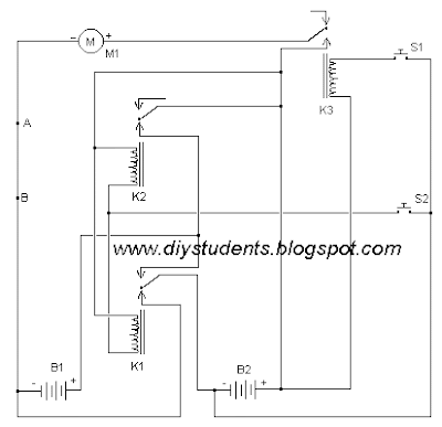
The simplest of all motor controllers (besides a straight on/off switch) is the contactor controller. I designed this contactor controller for use in my electric scooter project. It is based around three 12V relays, two 12V batteries, two switches and of course a motor. Having no silicon to "fry", it is quite reliable and robust. A contactor controller works by rearranging the two (or more) supply batteries between series and parallel. This gives the motor a slow speed (batteries in parallel, current adds) and a fast speed (batteries in series, voltage adds). This assures that both batteries are discharged equally. When the circuit is "at rest", the batteries are connected in parallel, which allows easy recharging.

Simple Servo Controller

Servo motors have many uses in everything from robotics to puppetry to photography and beyond. These little motors can position their output shaft to any position on command and hold that position. Most servos have a range of motion to about 210 degrees and thankfully are very easy to control with a simple circuit such as the one presented here. Using just a 555 timer and a few support components this circuit can control a servo through it's full rotation based on the position of a pot. This circuit was originally published in the Think Tank column of the October 1995 issue of Popular Electronics.

Pulse Width Modulation DC Motor Control


Often, people attempt to control DC motors with a variable resistor or variable resistor connected to a transistor. While the latter approach works well, it generates heat and hence wastes power. This simple pulse width modulation DC motor control eliminates these problems. It controls the motor speed by driving the motor with short pulses. These pulses vary in duration to change the speed of the motor. The longer the pulses, the faster the motor turns, and vice versa.

AC Motor Speed Controller

This AC motor speed controller can handle most universal type (brushed) AC motors and other loads up to about 250W. It works in much the same was a light dimmer circuit; by chopping part of the AC waveform off to effectively control voltage. Because of this functionality, the circuit will work for a wide variety of loads including incandescent light bulbs, heating elements, brushed AC motors and some transformers. The circuit tries to maintain a constant motor speed regardless of load so it is also ideal for power tools. Note that the circuit can only control brushed AC motors. Inductive motors require a variable frequency control.

Load Sensing Automatic Switch

Description

The circuit of the mains current detector is shown in Figure 1.  By using a few cheap diodes, a resistor, LED and LDR, a simple opto-isolated detector can be created.  This entire circuit dissipates very low power, and can safely be housed in a heatshrink wrapper to ensure that contact with live wiring is not possible.  This will also keep light away from the LDR.  These are cheap and easy to use.  I found that I could detect as little as 10mA of mains current with this circuit, and no distress was created at 0.5A.  The diodes will get very warm at higher currents.

Note that because of the 1A diodes used, this is the absolute maximum current of the switched load.  If a higher current is expected, you must use high current diodes to prevent failure.  I shall leave it to the reader and the local electronics supplier to select suitable devices.  Voltage rating is not important, as they are in series with the load.  Don't be tempted to use Schottky diodes to reduce the loss - you need the loss to turn on the LED.

Automatic Headlight Brightness Switch


Driving the highway with your high-beam headlights can really increase your visibility, but can be a blinding hazard for other drivers. This simple circuit can be wired into your headlight switch to provide automatic switching between high and low beam headlights when there is oncoming traffic. It does this by sensing the lights of that traffic. In this way, you can drive safely with your high-beams on without blinding other drivers.

Automatic Switch For Audio Power Amplifier

Circuit of an automatic switch for audio power amplifier stage is presented here. The circuit uses stereo preamplifier output to detect the presence of audio to switch the audio power amplifier on only when audio is present. The circuit thus helps curtail power wastage. IC1 is used as an inverting adder. The input signals from left and right channels are combined to form a common signal for IC2, which is used as an open loop comparator. IC3 (NE556) is a dual timer. Its second section, i.e., IC3(b), is configured as monostable multivibrator. Output of IC3(b) is used to switch the power amplifier on or off through a Darlington pair formed by transistors T1 and T2. IC3(a) is used to trigger the monostable multivibrator whenever an input signal is sensed. 
Click On Circuit to view Large

HEAT-SENSITIVE SWITCH

At the heart of this heat-sensitive switch is IC LM35 (IC1), which is a linear temperature sensor and linear temperature-to-voltage converter circuit. 
The converter provides accurately linear and directly proportional output signal in millivolts over the temperature range of 0°C to 155°C. It develops an output voltage of 10 mV per degree centigrade change in the ambient temperature. Therefore the output voltage varies from 0 mV at 0°C to 1V at 100°C and any voltage measurement circuit connected across the output pins can read the temperature directly. 
The input and ground pins of this heat-to-voltage converter IC are connected across the regulated power supply rails and decoupled by R1 and C1. Its temperature-tracking output is applied to the non-inverting input (pin 3) of the comparator built around IC2. The inverting input (pin 2) of IC2 is connected across the positive supply rails via a voltage divider network formed by potmeter VR1.
Click on Immage to view large

Intelligent switch

This intelligent switch circuit en- ables automatic switching on of an emergency light system during darkness in the event of mains failure. The mains power failure condition is detected by the section consisting of mains step-down transformer X1 followed by bridge rectifier comprising diodes D1 through D4 and smoothing capacitor C1. If the mains is available then it causes energisation of relay RL1 which has two sets of changeover contacts. 

Electronic Door Release

Description

This circuit is designed to operate an electrical door-release mechanism - but it will have other applications. Enter the four-digit code of your choice - and the relay will energize for the period of time set by C4 & R4. Use the relay contacts to power the release mechanism. The standby current is virtually zero - so battery power is a realistic option.

The circuit is drawn with a 12-volt supply - but it will work at anything from 5 to 15-volts. All you have to do is choose a relay suitable for the supply voltage you want to use. Replace the SPCO/SPDT relay with a multi-pole relay - if it suits your application.

Important: Do not use the "on-board" relay to switch mains voltage. The board's layout does not offer sufficient isolation between the relay contacts and the low-voltage components. If you want to switch mains voltage - mount a suitably rated relay somewhere safe - Away From The Board.

Keypad Switch No. 2

Description

This is a simplified version of the Universal Keypad-Operated Switch. I have modified the design to reduce the complexity of the circuit - and the number of components required. As a result - the code is somewhat less secure. However, there should be lots of situations where it will still be adequate. 

The circuit is drawn with a 12-volt supply - but it will work at anything from 5 to 15-volts. All you have to do is choose a relay suitable for the supply voltage you want to use. Replace the SPCO/SPDT relay with a multi-pole relay - if it suits your application. 


Important: Do not use the "on-board" relay to switch mains voltage. The board's layout does not offer sufficient isolation between the relay contacts and the low-voltage components. If you want to switch mains voltage - mount a suitably rated relay somewhere safe - Away From The Board. 


VCS using 555 Timer

Description

In this circuit the 555 timer is used in a novel way, as a voltage controlled switch.


Motor Reversing Circuit


Description

Motor cannot be switched from forward to reverse unless the stop switch is pressed first.

Voltage Comparator

Description

This circuit will provide an indication whenever the input voltage differs from two defined limits, V1 and V2. The limits are adjustable and the circuit made to trigger from the adjustable "window". 

Saturday 20 April 2013

Sound Operated Switch

Description

A sound operated switch with a relay driver.

Electronic Night Light


Description

This circuit for an electronic night light was submitted by Adam from Canada. I have provided the notes.